Introduction
When it comes to PCB (Printed Circuit Board) design, every decision impacts the performance, durability, and reliability of the final product. Whether you’re working on a consumer gadget, an industrial automation system, or IoT devices, following the right practices can make or break your project.
In this blog, we’ll explore the best things to do in PCB design, compare best vs. poor practices, and walk you through a real case study of Dimi Cube’s Flex PCB project engineered by Devomech Solutions.
Best Things to Do in PCB Design
1. Focus on Signal Integrity and Power Distribution
Signal integrity ensures that data signals travel without distortion, interference, or delays. Proper routing of high-speed signals, minimizing crosstalk, and using dedicated power and ground planes are crucial. Power distribution must be even and low impedance to avoid voltage drops and noise issues in sensitive components.
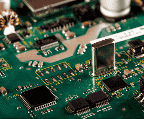
2. Ensure Proper Component Placement for Compactness and Accessibility
Good PCB layout starts with logical component grouping. Place power components near power inputs, keep analog and digital sections separate, and avoid unnecessary trace crossovers. This not only saves space but also improves debugging and rework accessibility. Poor placement often leads to longer traces, increased noise, and heat management issues.
3. Use Flexibility (Flex PCB) Where Design Constraints Demand Compact Performance
When space is limited like in wearables, IoT devices, or compact consumer electronics Flex PCBs are the go-to solution. They allow bending, folding, and compact stacking without sacrificing performance. However, proper bend radius and material selection must be considered to avoid mechanical stress failures.
4. Perform Rigorous Testing and Quality Assurance at Every Stage
Testing isn’t just the last step, it should be part of the entire design cycle. Continuity checks, EMI/ESD testing, power rail analysis, and stress tests are essential. This ensures the PCB won’t fail under real-world conditions. At Devomech, we integrate multiple test stages to guarantee performance before production.
5. Document Everything for Future Iterations and Improvements
A well-documented PCB design saves countless hours in troubleshooting and upgrading. This includes schematics, version control, Bill of Materials (BOM), and design files. Clear documentation makes collaboration smoother and supports scalability when new versions or product upgrades are required.
PCB Best Practices vs. Poor Practices
| Aspect | Best Practices | Poor Practices |
| Component Placement | Logical grouping, minimal crossovers, clear signal paths | Random placement, excessive via usage, overlapping traces |
| Power & Ground | Dedicated planes, low impedance, proper decoupling | No ground plane, poor decoupling, uneven distribution |
| Testing & Validation | Multiple test points, stress testing, quality check before final production | Minimal testing, ignoring EMI/ESD protection |
| Design Documentation | Clear schematics, version control, BOM updates | Missing files, incomplete BOM, no revision history |
| Thermal Management | Proper copper pours, thermal vias, heat sinks | Ignoring heat flow, no thermal analysis |
| Flex PCB Integration | Compact, reliable, stress-tested design | Ignoring bend radius, weak connections, mechanical stress points |
Case Study: Flex PCB in Dimi Cube Project
At Devomech Solutions, PCB design is not just about connecting circuits—it’s about engineering reliability and performance. Let’s dive into how we helped Dimi Cube bring its Cube+ Duo project to life with Flex PCB design.
From Schematic to Reality
Inside the Cube+ Duo PCB Journey, the challenge was to combine power, performance, and precision into a compact flex PCB without compromising reliability.
The Challenge
Every innovation starts with a question:
“How do we make power, performance & precision coexist in one compact board?”
Process & Rigorous Testing
To answer this, our engineers focused on testing and validating:
- Power Rail & Battery Charging
- Protection Circuits
- ESP-S3 Programming
- LCD Brightness & Push Buttons

Quality Assurance
Our QC process ensured:
- No shorts
- Perfect alignment
- Smooth continuity
The Result
The Flex PCB designed for Dimi Cube’s Cube+ Duo was compact, durable, and performance-oriented, an engineering solution that balances innovation with reliability.
Learn more about this project here: Flex PCB in Dimi Cube Project of Devomech Solutions
Conclusion
The best things to do in PCB design always come down to planning, precision, and performance testing. Whether you are designing for high-speed applications, IoT systems, or compact flex boards like the Dimi Cube project, following best practices ensures you avoid costly mistakes and build for long-term reliability.
At Devomech Solutions, we specialize in transforming schematics into reality with quality, precision, and innovation.
FAQs
Q1. What are the best practices for PCB design?
A: Best practices include careful component placement, ground planes, proper decoupling, thermal management, and thorough testing.
Q2. Why is testing so important in PCB development?
A: Testing ensures there are no shorts, continuity issues, or overheating problems, saving cost and preventing failures.
Q3. What is the role of Flex PCBs?
A: Flex PCBs allow compact designs with higher reliability, making them ideal for modern gadgets like wearables and IoT devices.
Q4. How does Devomech Solutions ensure PCB quality?
A: Through rigorous stress testing, quality checks, and aligning design with industrial standards before production.
Q5. What industries benefit most from advanced PCB design?
A: Consumer Electronics, industrial automation, IoT, healthcare devices, and renewable energy systems.
Q6. Can PCB design affect power efficiency?
A: Yes, optimized layouts, power rails, and ground planes directly impact energy efficiency and device lifespan.