

TL;DR
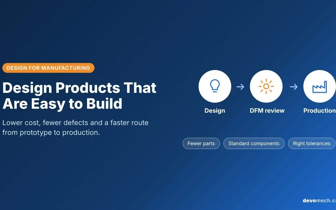
Design for manufacturing (DFM) means designing parts and products so they can be made reliably, quickly and at the right cost. Because most of a product’s cost is fixed by decisions made during design, DFM moves manufacturing knowledge to the start of the project. Simpler parts, standard components, sensible tolerances and process-specific design rules lead to fewer defects, lower unit costs and a faster route from prototype to production.
Introduction
Many products work perfectly as prototypes and then run into trouble at the factory. A housing that was easy to 3D print cannot be removed from an injection mould. A PCB that worked on the bench has a low assembly yield. A tolerance that looked harmless doubles the machining cost.
These problems rarely come from manufacturing itself. They come from design decisions made without production in mind. Design for manufacturing fixes this by asking “how will this be made?” at every design step, not after the design is finished.
This guide explains what DFM is, why it matters, its core principles, how it applies to common manufacturing processes and electronics, and how to build it into your product development process.
1. What Is Design for Manufacturing?
Design for manufacturing (DFM), also called design for manufacturability, is the practice of designing a product so it is easy and cost-effective to produce with the chosen materials, processes and equipment.
DFM is closely linked to design for assembly (DFA), which focuses on reducing the time and effort needed to put parts together. Together they are known as design for manufacturing and assembly (DFMA). Related “design for X” disciplines include design for testing (DFT), design for cost and design for serviceability.
DFM is not a single checklist. It is a way of working in which designers, engineers and manufacturers review a product together, early and often.
2. Why DFM Matters
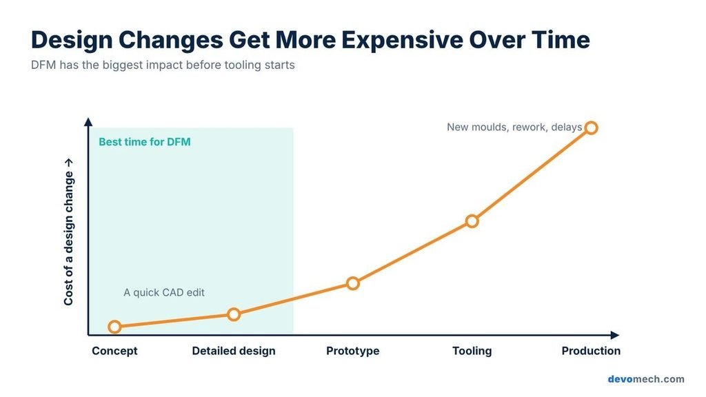
It is commonly estimated that around 70 to 80 percent of a product’s manufacturing cost is decided during design. Once tooling is cut and suppliers are chosen, changes become slow and expensive. A change that takes an hour in CAD can take weeks and a new mould after production starts.
Applying DFM early helps you:
- Lower unit cost: fewer parts, simpler geometry, cheaper materials and shorter cycle times.
- Improve quality and yield: designs that suit the process produce fewer defects and less scrap.
- Reduce tooling cost: simpler moulds and fixtures cost less and last longer.
- Speed up time to market: fewer redesigns and fewer surprises during the pilot run.
- Scale with confidence: a design that is easy to make at 100 units is far easier to make at 10,000.
3. Core DFM Principles
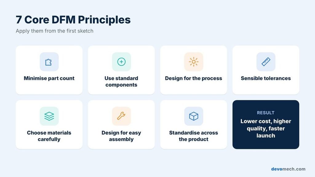
The details depend on the process, but a few principles apply to almost every product:
- Minimise part count: every part adds cost, assembly time and a potential failure point. Combine parts where function allows.
- Use standard components: off-the-shelf screws, connectors and electronic parts are cheaper, easier to source and well proven.
- Design for the process: each process has its own rules for wall thickness, radii, draft angles and hole sizes. Follow them from the first sketch.
- Specify sensible tolerances: tight tolerances raise cost quickly. Apply them only where function requires them.
- Choose materials carefully: balance performance, cost, availability and how easily the material can be processed.
- Design for easy assembly: use self-locating features, snap fits and a single assembly direction where possible, and make incorrect assembly impossible.
- Standardise across the product: reuse the same fasteners, materials and features to simplify sourcing and inventory.
4. DFM Guidelines by Manufacturing Process
Every manufacturing process has its own design rules. These are some of the most important ones to consider.
| Process | Key DFM guidelines | Common pitfall |
| Injection moulding | Uniform wall thickness, draft angles on vertical faces, ribs instead of thick sections, generous radii | Thick or uneven walls causing sink marks and warping |
| CNC machining | Standard tool sizes, internal corner radii, limited deep pockets, fewer setups | Sharp internal corners and very tight tolerances everywhere |
| Sheet metal | Consistent bend radii, holes away from bends, bend reliefs, standard gauges | Features placed too close to bends |
| 3D printing (production) | Self-supporting angles, minimum wall thickness, part orientation | Treating prototype-only designs as production-ready |
| Casting | Draft, uniform sections, fillets, planned parting lines | Abrupt thickness changes causing porosity |
For deeper detail on two of these processes, see our guides to sheet metal design and plastic mouldings.
5. DFM for Electronics and PCBs
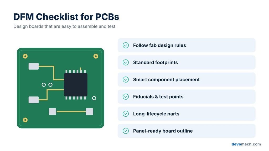
Electronic products need DFM too. A PCB that cannot be assembled or tested efficiently will drive up cost and failure rates. Key practices include:
- Follow the manufacturer’s design rules: minimum trace width, spacing, drill sizes and annular rings.
- Use standard footprints and packages: they suit automated pick-and-place and reduce assembly defects.
- Plan component placement: consistent orientation, enough clearance and components on one side where possible.
- Add fiducials and test points: they enable automated optical inspection and in-circuit or functional testing (DFT).
- Check component lifecycle: avoid parts that are near end-of-life or available from only one supplier.
- Think about panelisation: design the board outline so it can be efficiently panelised and separated.
Our high-quality PCB design guide covers PCB layout best practices in more detail.
6. How DFM Fits Into the Product Development Process
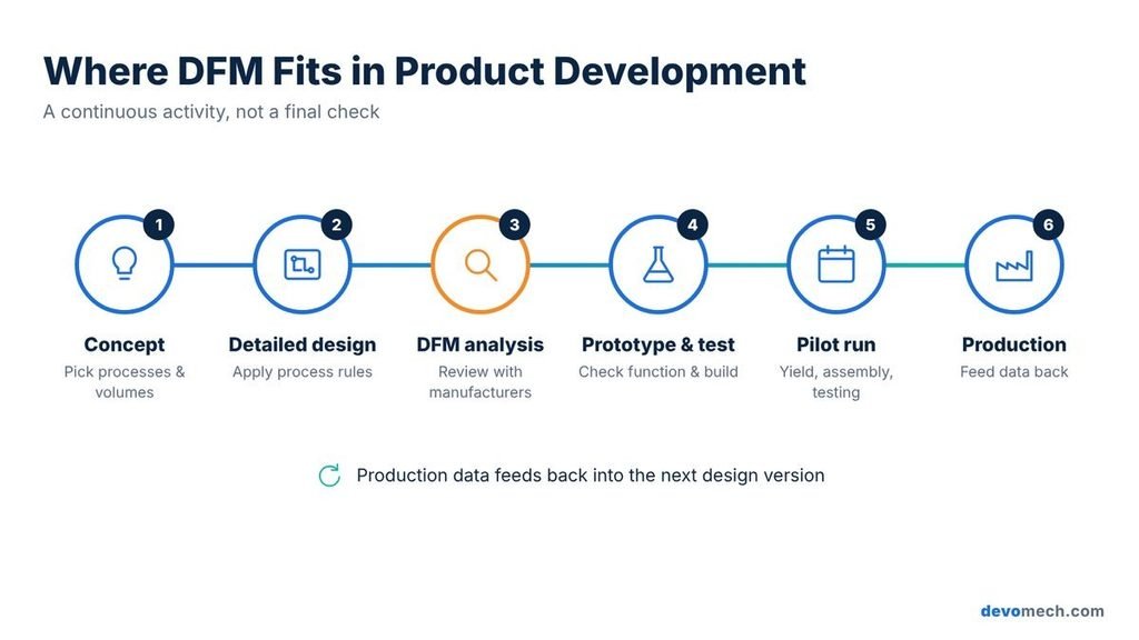
DFM works best as a continuous activity rather than a single review at the end:
- Concept: choose likely manufacturing processes and target volumes early, as they shape the whole design.
- Detailed design: apply process-specific rules in CAD and keep tolerances and part count under control.
- DFM analysis: review the design with manufacturers and toolmakers, using simulation such as mould-flow analysis where useful.
- Prototype and test: validate both function and manufacturability. Our guide to product prototype development explains this stage.
- Pilot run: produce a small batch to check yield, assembly time, test coverage and supplier quality.
- Production and improvement: feed production data back into the design for future versions.
7. Common DFM Mistakes to Avoid
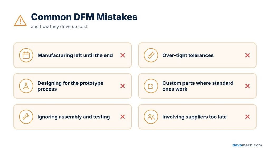
- Leaving manufacturing until the design is “finished”: late changes are slow and costly.
- Over-tightening tolerances: precision where it is not needed adds cost without adding value.
- Designing for the prototype process: a 3D-printed part rarely transfers directly to injection moulding.
- Using custom parts where standard ones would work.
- Ignoring assembly and testing: parts that are cheap to make can still be slow to assemble or impossible to test.
- Not involving suppliers early: manufacturers often suggest simple changes that save significant cost.
8. How to Choose a DFM Partner
Good DFM services combine design engineering with practical manufacturing experience. Look for a partner that offers:
- Multi-disciplinary engineering: mechanical, electronics and firmware working together.
- Process knowledge: experience with the manufacturing processes and volumes your product needs.
- Structured DFM reviews: documented analysis with clear, prioritised recommendations.
- Manufacturer relationships: links with toolmakers, PCB assemblers and contract manufacturers.
- Support through production: help with pilot runs, quality checks and engineering changes.
Frequently Asked Questions
What is the difference between DFM and DFA?
DFM focuses on making individual parts easy and affordable to produce. DFA focuses on making those parts easy to put together. DFMA combines both approaches.
When should DFM start?
As early as possible, ideally at the concept stage. The earlier manufacturing is considered, the cheaper it is to change the design.
Does DFM only matter for high-volume products?
No. DFM matters at any volume, although the right choices change. Low-volume products may favour machining or sheet metal, while high volumes often justify moulding and custom tooling.
What is a DFM analysis?
A DFM analysis is a structured review of a design against the chosen manufacturing process. It identifies features that increase cost, cause defects or slow production, and recommends changes.
Can DFM be applied to an existing product?
Yes. Many companies use DFM to redesign existing products to reduce cost, improve quality or move production to a new process or supplier.
Next Steps: Making Your Product Ready for Production
- Define your target unit cost, production volume and markets.
- Identify the likely manufacturing processes for each major part.
- Review your design for part count, tolerances and standard components.
- Run a DFM analysis with experienced engineers and manufacturers.
- Validate the design with a prototype and a pilot run before full production.
How Devomech Can Help
Devomech combines mechanical design, electronics, PCB design and firmware engineering under one roof, with manufacturing considered from the first concept. Our DFM services include design reviews, design optimisation, material and process selection, and support from prototype through pilot production. Learn more about our hardware product design services.
Ready to make your product easier and more affordable to build? Contact Devomech to discuss your design and production goals.
Sources & References
- Boothroyd, G., Dewhurst, P. and Knight, W.: Product Design for Manufacture and Assembly (CRC Press)
- IPC-2221: Generic Standard on Printed Board Design
- Devomech website: devomech.com